Design workflow
The conceptual development of compas_3gs is based on key open problems in 3D graphic statics, as outlined in 1.
These problems are addressed from the perspective of a designer in practice, with particular focus on maximising the applicability and usability of the mathematical theories behind the reciprocal relationship of form and force diagrams in real-world applications.
The suggested design workflow using compas_3gs is summarised as follows.
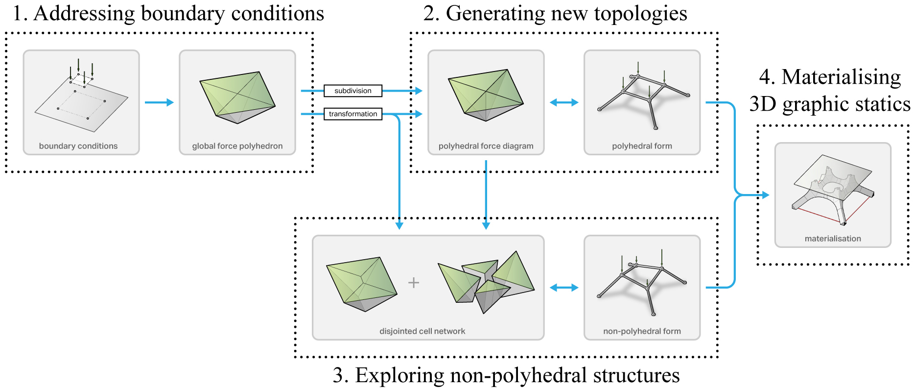
1. Addressing boundary conditions
During the beginning stages of a project, the only known information to the designer are typically the type of loading the structure will carry (applied load locations and magnitudes) and the physical constraints of the site (i.e. support locations, types, allowable reaction force magnitudes, etc.). Before any design explorations using 3D graphics can take place, the quantitative (force magnitudes) and spatial (force locations) site constraints, which are unique for each project, need to be incorporated during the construction of the initial global force polyhedron.
2. Generating new topologies
Once the global force polyhedron has been constructed, various subdivision schemes can be applied to generate and explore structural topologies. Subdivision of internal polyhedral cells increases the complexity of the structural topology without changing the initial boundary conditions (2). As a result of subdividing a polyhedral cell, a single member of the corresponding form diagram is replaced with multiple members that together carry the same magnitude of axial force as the replaced member. Therefore, subdivision can be an effective method for addressing buckling, although it is a trade-off for challenging fabrication due to the diminishing member-to-member angles as the increasing number of members. Subdivision schemes are highly dependent on the initial funicular topology embedded within the global force polyhedron. The repeated subdivision of a given global force polyhedron generally results in the refinement of the same, initial funicular form. In addition to subdivision, additive polyhedral transformations can generate new topologies by enabling the designer to introduce new members to a structure in a more non-automated, sculptural manner (3).
3. Exploring non-polyhedral structures
The reciprocal relationship between the polyhedral form and force diagrams restricts design explorations to structures that are polyhedral in its geometry (i.e. subdivided tree structures, faceted domes, polyhedral mesh or surface structures, crystalline aggregations, etc.). Inherent geometric constraints of polyhedral form and force diagrams make it impossible to construct force diagrams for spatial structures in equilibrium which may be non-polyhedral in its geometry (i.e. structures with overlapping members, non-planar faces, etc.). Polyhedral constraint is beneficial for applying global manipulations and transformations, but ultimately limits the range of structural typologies that can be explored.
In current implementations of 3D graphic statics, polyhedral force diagrams are computationally constructed as volumetric meshes with matching contact faces and shared vertex coordinates between any pair of adjacent cells. In a disjointed cell network, any pair of adjacent cells are constrained to have the same contact face orientations and areas, but each with its own vertex locations and topology. Cell networks allow integration of quantitative, force-driven constraints and exploration of new typologies that are not realisable with volumetric-mesh-based applications of 3D graphic statics.
4. Materialising 3D graphic statics
The final step of the 3D graphic statics design workflow is the materialisation of the network of lines that represents the form diagram. The form diagrams in graphic statics applications represent the topology and geometry of equilibrium structures, but they do not carry any material information. While complex structural toplogies can be quickly generated using the 3D graphic statics design workflow, addressing the materialisation and practical feasibility of complex network of lines in space, especially the nodes, is important in expanding 3D graphic statics applications beyond computational form-finding explorations of abstract shapes.
Existing “wire thickening” methods can be acceptable for small scale applications where the geometric complexity of the components can be resolved through additive fabrication methods such as 3D printing. However, as the structure increases in scale, a more generalised method for rationalising the fabrication geometry of complex spatial nodes is needed for both economic and practical reasons. By exploiting the inherent polyhedral properties of form and force diagrams used in 3D graphic statics, a more feasible method for materialising spatial networks of lines can be developed.
References
- 1
Lee J. (2018). Computational Design Framework for 3D Graphic Statics. PhD thesis, ETH Zurich, Zurich, Switzerland.
- 2
Akbarzadeh, M., T. Van Mele, and P. Block (2014). Compression-only form finding through finite subdivision of the external force polygon. In Proceedings of the 2014 International Association for Shell and Spatial Structures (IASS) Symposium, Brasilia, Brazil.
- 3
Lee, J., T. Van Mele, and P. Block (2016). Form-finding explorations through geometric transformations and modifications of force polyhedrons. In Proceedings of the 2016 International Association for Shell and Spatial Structures (IASS) Symposium, Tokyo, Japan.